Grid Signals
In the Bitwig Studio Grid, there aren’t any distinct types of signals like in some other environments. All signals are processed, sent, and received at audio rate, and any output can be connected to any input of any module, always producing a result. This is quite different from systems like Pure Data, where signals are separated into types like messages, data, and audio, each processed differently and not always interchangeable.
In the Grid, everything behaves more like a Eurorack modular system. This design has its advantages, like flexibility, but also some downsides - primarily that treating all signals as audio signals can be CPU-intensive. While there are no formal signal types, there are different kinds of signals in the Grid, which behave differently and have unique ranges and characteristics:
All Signals are Stereo! #
Another unique feature of signals in the Bitwig Grid is that all signals are stereo by default. This means every signal actually has two channels - left and right. Normally, both channels carry identical data, which effectively makes it a mono signal when they’re perfectly matched.
However, you can take advantage of this stereo structure by using various splitter modules like Stereo Split to route the left and right channels separately, process them differently, and then merge them back together. This opens up a lot of creative possibilities for stereo effects.
For example, all oscillators in the Grid are also stereo. If you place a Sine Oscillator module, it outputs a stereo signal by default. If you send pitch data where the left and right channels have different values, the oscillator will generate different frequencies for each channel, creating a dual-pitch output.
This allows you to send two independent signals through a single cable, which can be super useful for complex sound design. I actually demonstrated this in a video once, and people found it pretty interesting!
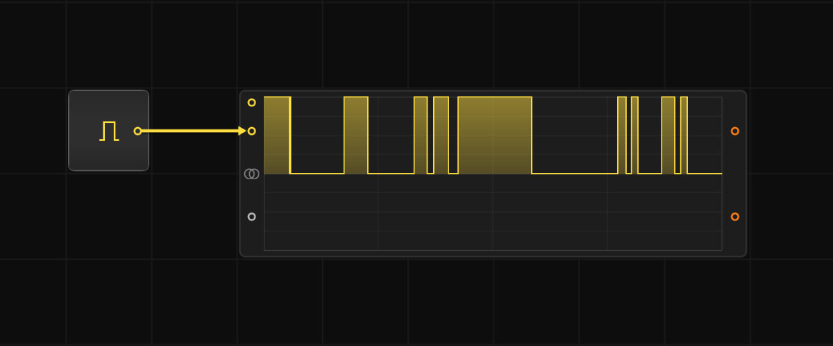
1. Gate Signals #
- Unipolar: Values switch between 0 (off) and 1 (on).
- Typically used to represent triggers, such as when a note starts or stops.
- Usually marked with yellow.
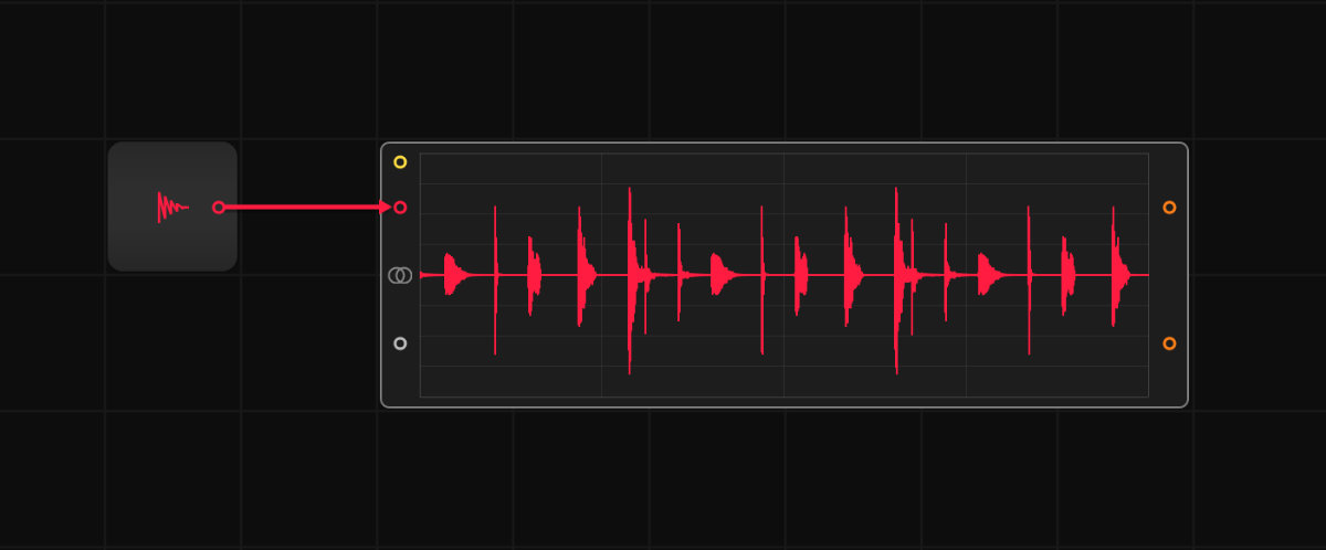
2. Audio Signals #
- Bipolar: Range spans from -1 to +1.
- Designed for audio or modulation. These signals update at audio rate, allowing for very fast changes.
- Marked with red.
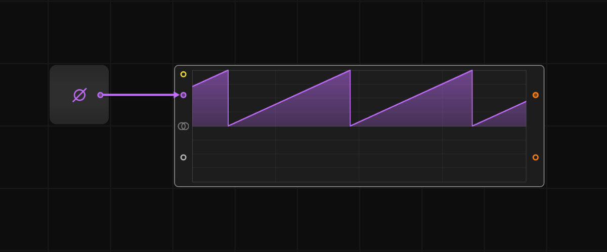
3. Phase Signals #
- Unipolar Values increase steadily from 0 to 1 (or to be specific 0.99), then reset back to 0. This pattern repeats over time.
- Commonly used to represent position in a sequencer or to drive oscillators.
- Marked with purple and usually look like ramps.
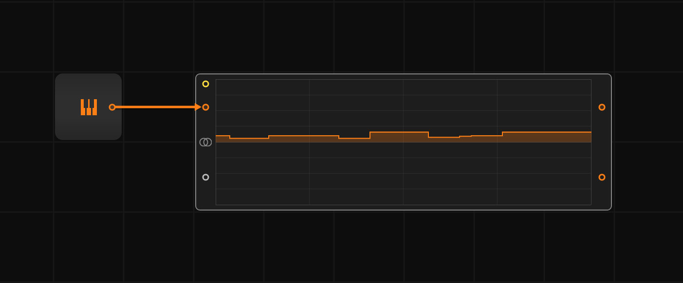
4. Pitch Signals #
- Bipolar: Range also spans -1 to +1, but values represent musical notes.
- 0 corresponds to C3 (middle C in Bitwig).
- Positive values go up in octaves (e.g., +1 is C13).
- Negative values go down (e.g., -1 is C-7).
- one semitone up (+1sm) equals to +0.008 in value.
- one octave up (+12sm) equals to +0.100 in value.
- Used to control the pitch of oscillators or to map notes in generative patches.
- Marked with orange
5. Float Signals #
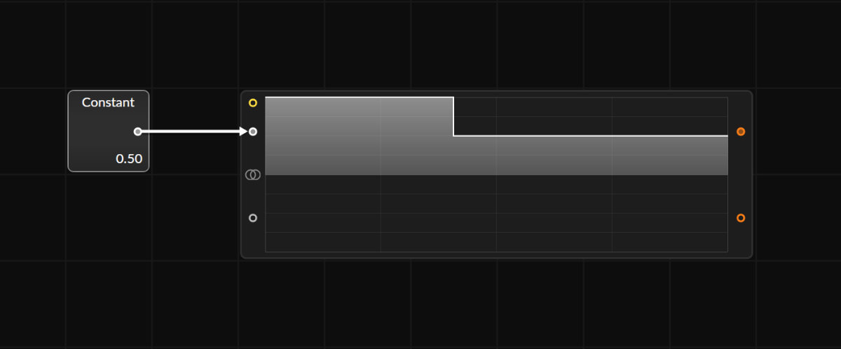
- Created using modules like Constant.
- Have a larger range than most other signals (e.g., -10 to +10 or more).
- Typically marked with white, and their behavior is useful for controlling parameters outside the -1 to +1 range.
Flexibility Across Signals #
One of the coolest aspects of the Grid is that any signal can be connected to any input, even if it wasn’t designed for that. For example:
- A Phase Signal can be sent to a pitch input, causing an oscillator to sweep its frequency slowly from C3 to the highest octave as the phase ramps from 0 to 1.
- Similarly, a Gate Signal could be connected to an audio input, which might result in a click every time the gate turns on.
This universal compatibility is key to the Grid’s modularity and what makes it so enjoyable and creative. It’s very similar to working with an analog modular system, where experimentation and unexpected results are part of the process.
Conversion #
There are several modules in the Grid that help convert one signal type into another. This often works through simple range mapping or transfer functions. For example, if you want to convert an audio signal into a phase signal, you can use the Wrap module:

This conversion doesn't check whether the signal makes logical sense - it simply projects all values outside the range of 0 to +1 (or 0.99) back into the allowed range. For example:
- -0.5 becomes +0.5
- +2.3 becomes 0.3
- important: +1 becomes 0 because the max value of the phase is technically +0.99 and not +1
No matter what values you feed in, the output will always stay between 0 and +1 (or 0.99), as phase signals operate strictly in this range.

You could also use the Bi→Uni module, which converts bipolar signals into unipolar ones differently. Here’s how it maps values:
- +1 stays +1
- 0 gets shifted to +0.5
- -1 becomes 0
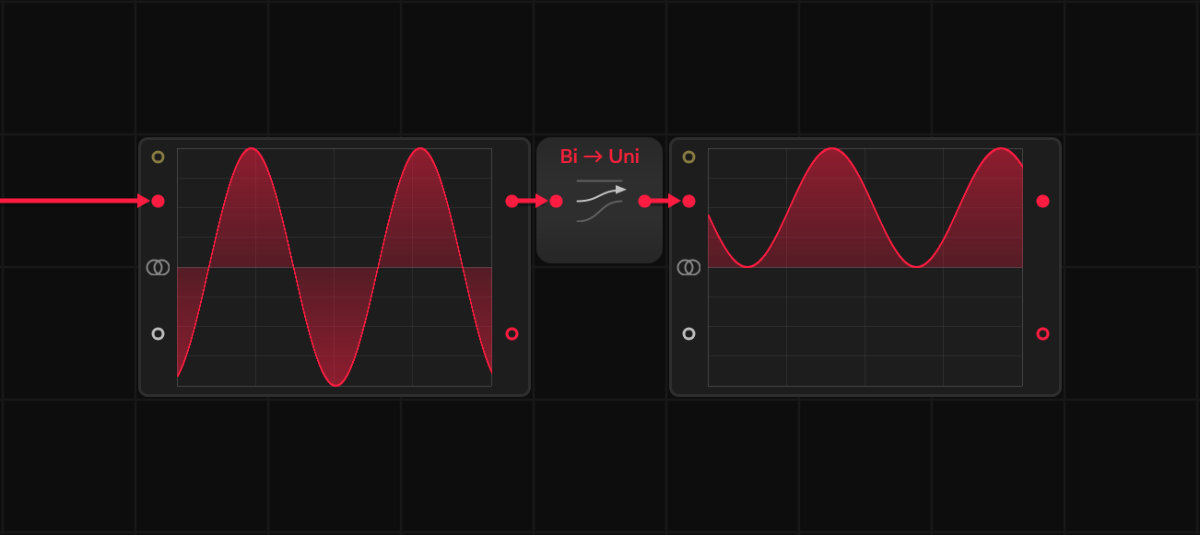
All values between 0 and -1 are shifted into the unipolar range of 0 to +1. However, this module doesn't limit the range strictly either. If you input a value like -2, it will return -0.5, which falls outside the intended unipolar range.
But the module simply claims to convert bipolar signals into unipolar ones, and since bipolar signals typically range between -1 and +1, you won't get a proper phase signal if you feed it incorrect values.
However, this isn’t really an issue in the Grid because most Phase In inputs already have an internal Wrap function. Still, it's good to be aware of how this works!
▶ Next Lesson: Creating Patches
◀ Previous Lesson: Module Features
▲ Bitwig Grid Course Overview