Bitwig Filters Explained: Which One Should You Use?
Article | Sep 09, 2026
A practical guide to the ten filters shared by The Grid and Filter+: where their ideas come from, what makes them useful, and starting points for basses, pads, percussion, vocal textures, and feedback experiments.
You put a filter after an oscillator, open the menu, and find Low-pass LD, Low-pass MG, Sallen-Key, SVF, XP, and several names that say even less about their sound. Where do you start?
Start with the job. A bass that needs a rounded cutoff movement, a pad that needs shifting holes in its spectrum, and a noise burst that needs to become a plucked string call for different tools.
This guide covers the ten filter modules shared by The Grid and Filter+, followed by the four additional utilities in the Grid's Filter category. The recommendations are starting points for your own patches. Source material, input level, resonance, and modulation all affect the result.
The diagrams illustrate basic filter shapes and signal flow, so you can connect what a control does with what you hear.
The filter menu at a glance #
All ten filters below are available in both The Grid and Filter+. Bitwig groups them into Structural, Inspired, and Character families. Bitwig's Filter+ reference
| Filter | Family | Useful first experiment |
|---|---|---|
| Low-pass LD | Structural | Shape a synth voice; compare gentle and steep low-pass slopes |
| Sallen-Key | Structural | Compare resonant low-pass, high-pass, and band-pass shaping |
| SVF | Structural | Make a moving band-pass, a wah sound, or a resonant ping |
| Comb | Structural | Turn a short noise burst into a pluck or metallic resonator |
| Low-pass MG | Inspired | Add Moog-style filtering and drive to a bass or lead |
| XP | Inspired | Explore unusual filter shapes on a sustained pad |
| Vowels | Inspired | Make a bright synth articulate vowel sounds |
| Fizz | Character | Add shifting, phaser-like detail to a sustained texture |
| Rasp | Character | Give a bass or lead a moving growl or sharper edge |
| Ripple | Character | Explore feedback, rough resonances, and subharmonic effects |
Shape first, character second #
Low-pass, high-pass, band-pass, and notch describe what happens to the spectrum. Ladder, Sallen-Key, and state-variable describe different ways of building a filter. Several designs can produce a low-pass response and still behave differently when you raise resonance or drive them harder.
- Low-pass: reduces the top end. Useful for darkening sounds and shaping the attack of a synth voice.
- High-pass: reduces the bottom end. Useful for thinning a layer or making space below it.
- Band-pass: keeps a band between the lows and highs. Try it for nasal leads, telephone-like sounds, and tuned noise.
- Notch: removes a band while keeping frequencies above and below it. Try a moving notch when you want animation without closing down the entire top end.
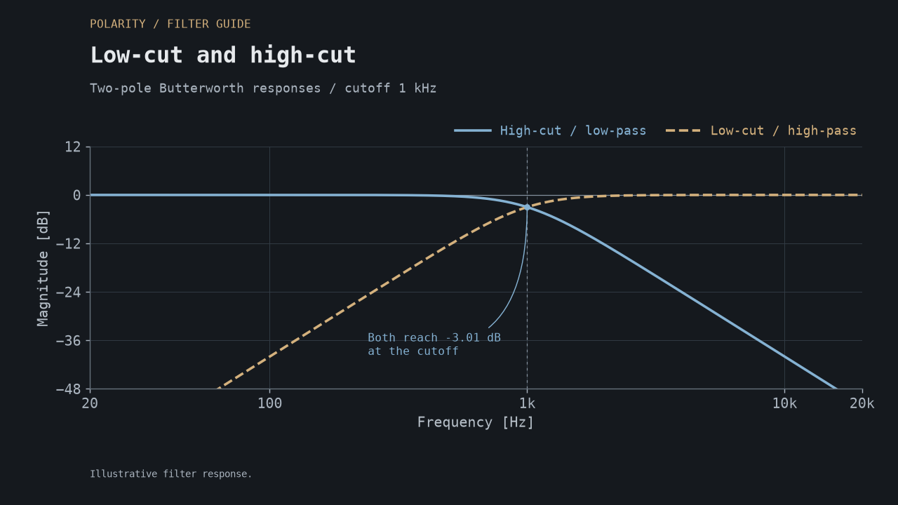
A high-cut is a low-pass; a low-cut is a high-pass. These two Butterworth examples share the same cutoff and slope.
Slope determines how strongly the filter removes frequencies beyond its transition region. A conventional two-pole low-pass approaches 12 dB per octave; four poles approach 24 dB per octave. Fewer poles often leave more upper detail, while more poles separate the retained sound more strongly from the removed frequencies. Moog's introduction to subtractive synthesis
Resonance emphasizes a region around cutoff. Drive changes how hard the signal hits the filter's nonlinear behavior. Together, they can turn ordinary tone shaping into part of the sound source itself.
Low-pass LD: choose how much top end to keep #
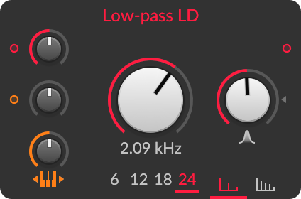
LD is a flexible ladder low-pass. The ladder family gets its name from the arrangement of stages in the circuit, and is strongly associated with Moog synthesizers. Bitwig places LD in its Structural family; the explicitly Moog-inspired choice is MG.
LD lets you choose slopes of 6, 12, 18 or 24 dB per octave, plus Symmetric or Asymmetric nonlinearity. That makes it a useful starting point when you know you want a low-pass but have not decided how much brightness or coloration the patch needs. The LD module reference covers these controls.
Try this: send a saw wave through LD with a short cutoff envelope. Compare two and four poles at low resonance. Listen to the upper buzz during the decay, then introduce drive. On a layered pad, the gentler setting may leave useful detail; on a short bass, the steeper setting may give you a more focused envelope movement.
Choose LD when changing the slope is part of finding the sound.
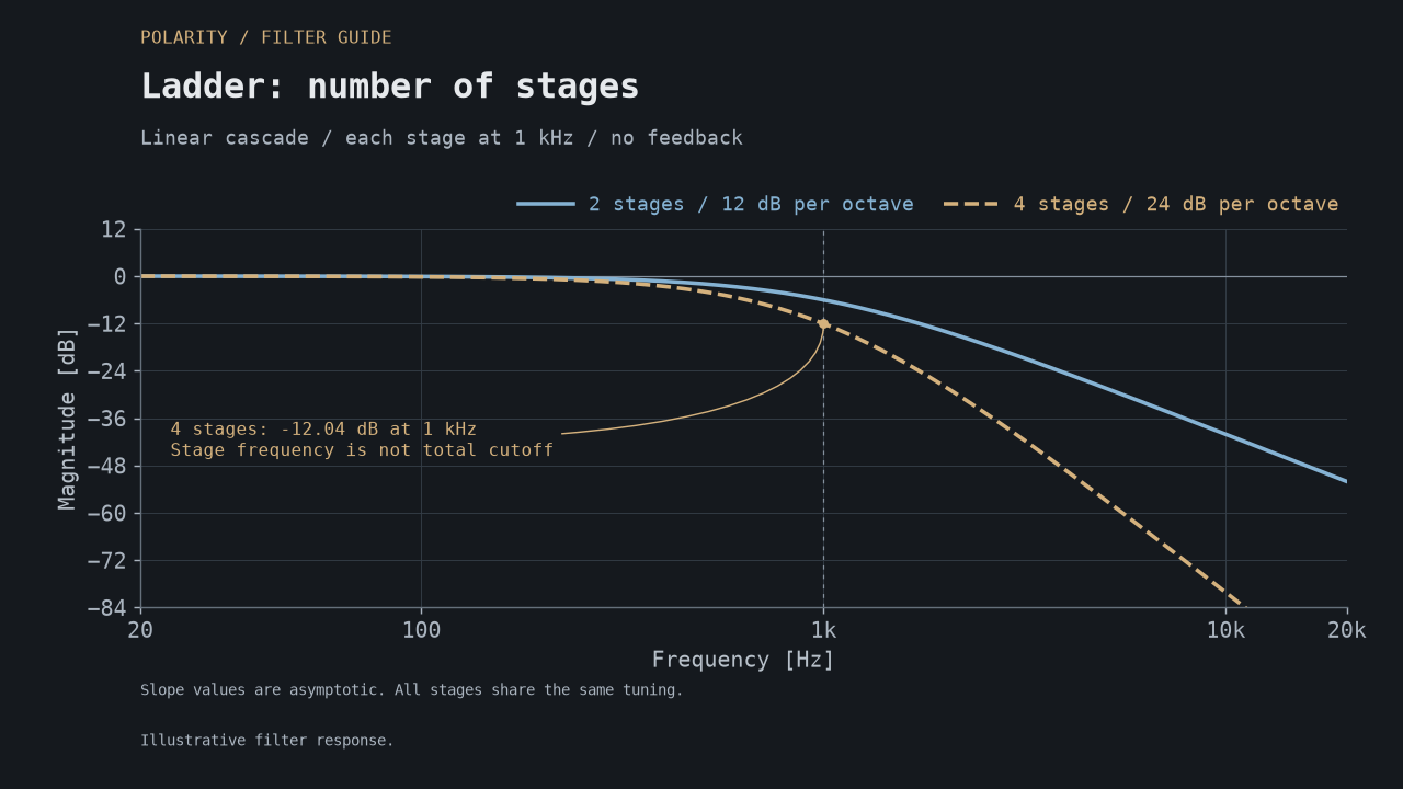
Each stage here is tuned to 1 kHz. The complete four-stage cascade is already about 12 dB down at that frequency: stage tuning and the complete filter's -3 dB cutoff are different quantities.
Low-pass MG: Moog-style basses and leads #
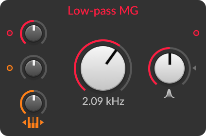
Bitwig describes MG as a Moog-inspired low-pass with drive coloration. The Minimoog Model D is a familiar hardware reference for this family: its manual describes a four-pole ladder low-pass. This is historical context; Bitwig's description does not establish an exact Model D emulation. Bitwig's module reference, Moog's Minimoog manual
MG is a sensible first audition for a rounded synth bass, a driven lead, or a sound where cutoff movement should feel like part of the instrument. Its fixed four-pole response keeps the choice simple.
Try this: use one saw oscillator, moderate resonance, and a short filter envelope. Increase Drive in small steps and compensate the output volume afterward. Listen for the point where the attack gains character without losing the body you need.
Pay attention to the fundamental as you raise resonance. If the bass becomes too thin, try less resonance before adding more drive or EQ. Check it against the kick, where that change matters most.
MG and LD use different resonance mappings and place saturation differently. MG has a fixed four-stage output, while LD provides selectable taps and character options. Compare their results by ear and match output loudness; copying the same knob positions does not make the two filters equivalent.
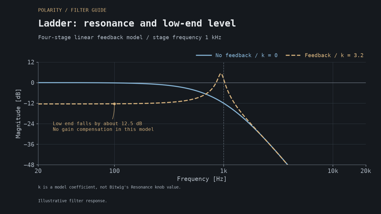
An ideal ladder example: more resonance changes the balance between the cutoff peak and the bass. Listen to the fundamental as well as the peak.
Sallen-Key: a versatile family with many slopes #
The name comes from R. P. Sallen and E. L. Key, who introduced the circuit in 1955 at MIT's Lincoln Labs. It became a widely used filter topology. Analog Devices' filter design note
There is a connection to synthesizer history: Doepfer traces its Steiner-derived and MS-20-derived designs back to this broader circuit family. That makes the Korg MS-20 a useful historical relative, but it does not make every Sallen-Key filter an MS-20 clone. Doepfer's circuit comparison
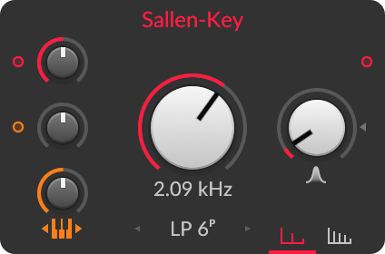
Bitwig's version offers 16 low-pass, high-pass, and band-pass configurations. Older tutorials may call it Low-pass SK; the expanded Sallen-Key module arrived in Bitwig 4.3. Bitwig 4.3 release notes
The menu lists LP and HP at 1, 2, 3, 4, 6 and 8 poles, plus BP at 2, 4, 6 and 8 poles. Its character choices are Symmetric and Asymmetric.
Try this: run a drum loop through a high-pass mode, add a little resonance, and slowly move cutoff through the lower mids. Then try a band-pass on the same loop for a thinner, more focused layer. Use Drive and the available character options to explore how restrained or rough that layer should become.
Choose Sallen-Key when you want to compare several shapes and slopes within one module. Its flexibility is a more useful starting point than assuming it must always sound aggressive because of its hardware relatives.
With band-pass filters, consider both flanks. A four-stage high-pass followed by a four-stage low-pass gives approximately 24 dB per octave on each side. The total number of poles is different from the slope of either individual flank.
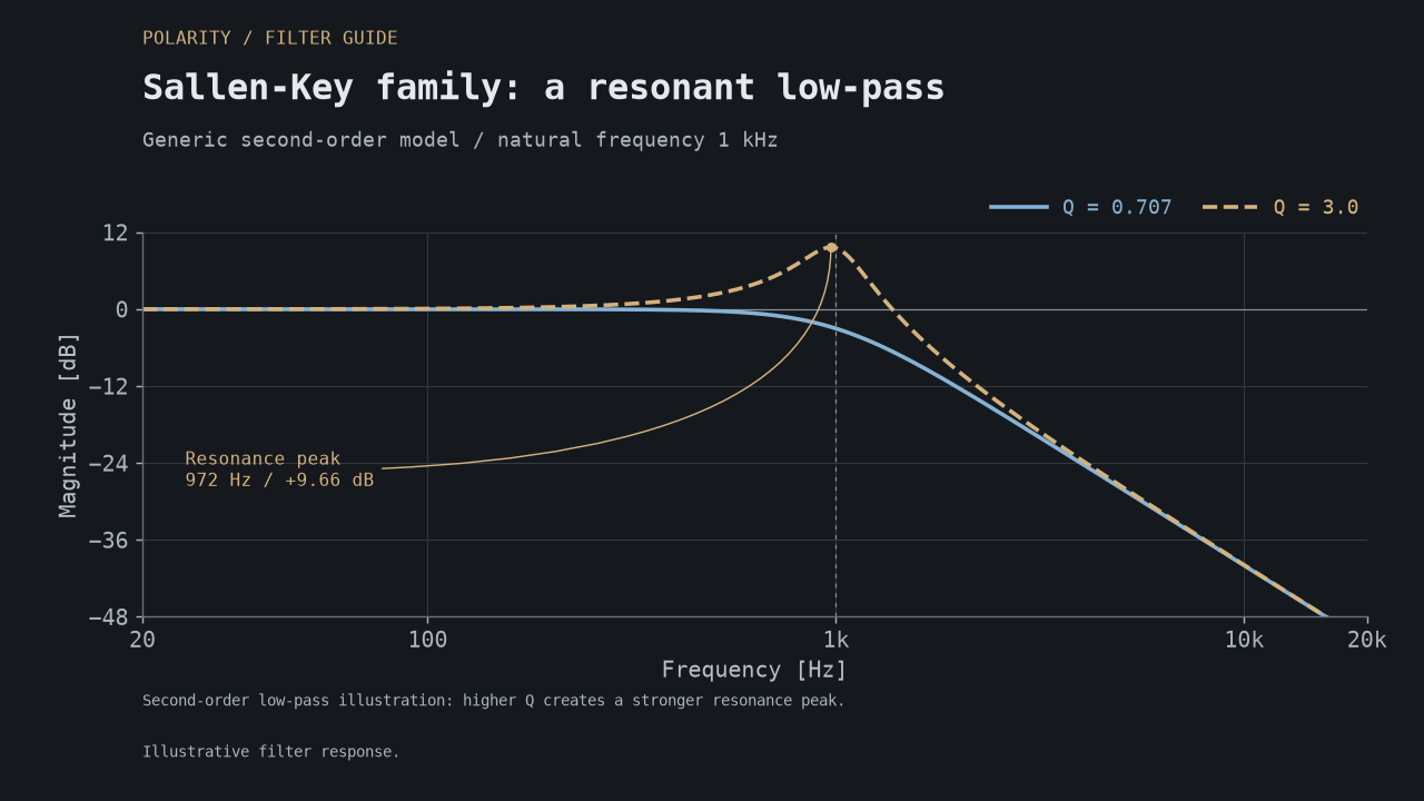
A textbook low-pass example from the Sallen-Key family: increasing Q introduces a peak. Its natural frequency stays at 1 kHz, while the peak sits slightly below it.
SVF: an everyday multimode starting point #
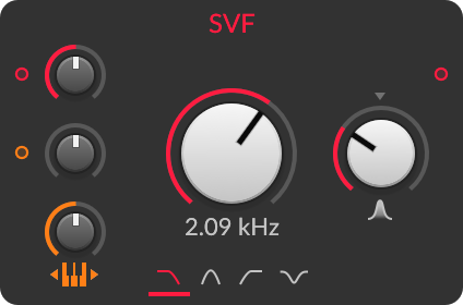
SVF means state-variable filter. This family provides several familiar responses from a common circuit structure. The Oberheim SEM is a well-known synthesizer example; Oberheim also identifies the SEM lineage in the state-variable filter of its OB-6. This establishes a family relationship, not a claim that Bitwig's SVF models that instrument. Oberheim's OB-6 description
SVF offers Low-pass, Band-pass, High-pass and Notch. Choose it when the shape and its movement are the main decisions.
Try this: select band-pass, feed it a bright oscillator or noise, and modulate cutoff with a slow triangle LFO. Start with little resonance for a broad sweep; raise it to make the moving band more obvious. An envelope follower can turn the same idea into an input-sensitive wah effect.
For percussion, excite a resonant setting with a short burst and listen to the decay. The SVF reference provides a starting point for these experiments.
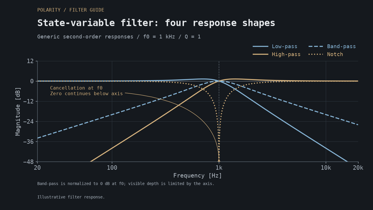
The band-pass retains the middle; the notch removes it. These illustrative shapes use a band-pass peak of 0 dB for comparison. Match output loudness when switching modes in your patch.
XP: explore the Oberheim multimode idea #
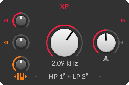
Bitwig identifies XP as Oberheim-inspired, with 15 configurations. The historical reference that fits this approach is the Oberheim Xpander: its original manual documents 15 modes, including low-pass, high-pass, band-pass, notch, phase-shift, and combined responses. The Xpander connection is an informed identification of the design lineage; Bitwig's public description names Oberheim more generally. Bitwig's Filter+ reference, Xpander owner's manual, "The Xpanded Filter"
XP is worth opening when a pad needs a different spectral shape. Its appeal is the range of responses you can explore while keeping the same source and modulation.
The menu includes one- through four-pole low-pass and high-pass choices, two- and four-pole band-pass, Peak, Notch, and three combinations: HP 2P + LP 1P, HP 1P + LP 2P, and HP 1P + LP 3P. Here P means poles. Try the combined shapes when a plain low-pass removes too much of the texture you want to keep.
Try this: hold a rich chord, reduce resonance, and audition the modes before adding cutoff movement. Choose a shape that leaves the right parts of the chord audible, then apply a slow LFO. Compare against LD if the result becomes too hollow or loses its role in the arrangement.
The SEM and Xpander illustrate different approaches within Oberheim's history. "Oberheim filter" alone does not tell you which response to expect.
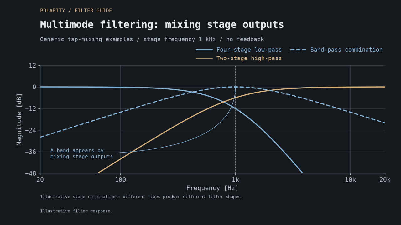
Illustrative combinations of filter-stage outputs: changing the mix creates different shapes. Audition XP's modes to find the right balance of body, brightness and movement.
Comb: turn excitation into an instrument #
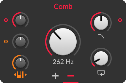
A comb filter creates a repeating pattern of peaks and dips through a short delay and signal combination. With feedback, that delay can ring. This connects it to Karplus-Strong-style plucked-string synthesis, where a short excitation circulates through a damped delay loop. Stanford's Karplus-Strong explanation
The useful distinction is musical: Comb can give a sound a pitched, string-like or metallic resonance. It does not simply darken an oscillator.
Try this: send a very short noise burst into Comb, increase the Feedback time gradually, and enable pitch tracking. Lower Damp for a darker decay. You now have the beginning of a playable pluck. On a drum loop, use a shorter Feedback time and blend in a small amount for resonant coloration.
Despite its name, Feedback is a time control, ranging from zero to eight seconds. Its nonlinear scale puts one second halfway through the control range. Damping and Drive also affect the audible decay. Positive and Negative are separate Feedback Polarity choices.
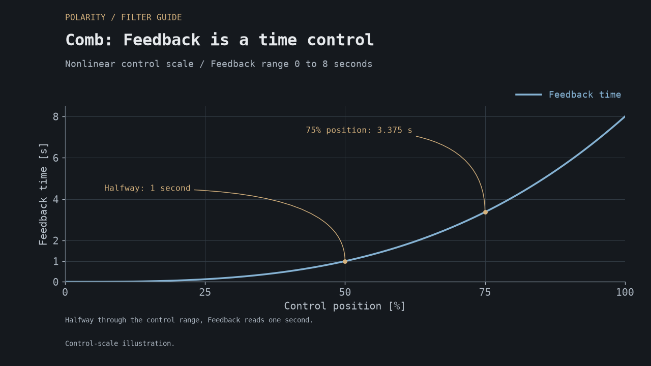
At 25%, 50% and 75% of the control range, Feedback reads 0.125, 1 and 3.375 seconds. This graph shows the control scale.
Treat cutoff as a tuning control here. A sweep can sound like an instrument changing pitch. My physical modeling lesson walks through the noise-burst patch.
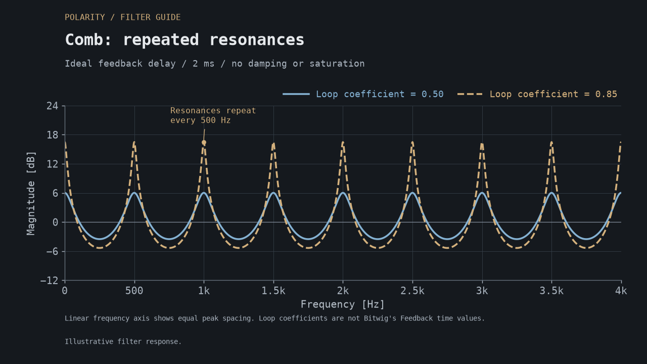
A 2 ms delay gives this ideal feedback comb resonances every 500 Hz. Higher feedback strengthens the peaks. The model's 0.5 and 0.85 values are loop coefficients, not Bitwig Feedback times or knob positions. The frequency axis is linear to make the equal spacing visible; damping and saturation are omitted.
Vowels: give a synth a mouth #
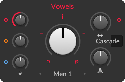
Vowels takes its inspiration from the resonances of the human vocal tract. Multiple emphasized frequency regions, called formants, help make a sound recognizable as a vowel.
Bitwig lets you choose vowel positions and blend between them, with different voice profiles and filter structures. You supply the audio; the filter supplies the changing resonances. Bitwig's Vowels reference
Try this: feed it a saw wave, select contrasting vowel sounds, and move Blend slowly. Map Blend to an envelope for articulation on each note, or to a controller for a playable talking lead.
Start with a harmonically rich source. A pure sine provides little material for the filter to emphasize. Keep the formants relatively steady while changing oscillator pitch for a more consistent vocal identity; move the formants deliberately for changes in apparent size or more synthetic voices.
Blend moves between vowel settings. Structure gives you Cascade, LP/BP and LP/BP/HP: different ways of connecting and mixing the filters. Compare the structures with Blend held still, and recheck loudness after each change.
For a useful starting point, set Resonance to 100%. Its scale runs logarithmically from 10% to 1000%, with 100% in the middle. Choose a vowel profile, then raise Resonance for sharper formants or lower it for a broader sound.
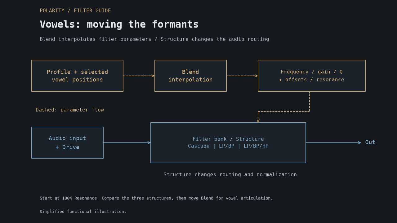
Simplified functional illustration: gold dashed arrows represent control changes; blue arrows represent audio. Blend moves the formant settings, while Structure changes how the filters work together.
Fizz: movement inside a sustained sound #
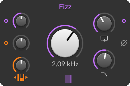
Fizz belongs to Bitwig's own Character designs, introduced in 5.1. It combines filtering with moving internal resonances. Color changes their placement, which can produce formant-like or phaser-like movement. Bitwig's Character filter demonstrations explore this family in practical patches.
Fizz combines two filter systems with phase-shifting, EQ and saturation in their feedback paths. Color and Alt reshape those relationships. Move Color by hand or with an LFO for a changing texture.
Try this: send a sustained pad or filtered noise into Fizz. Keep Main Cutoff fairly open, add feedback gradually, and move Color slowly. Then move Feedback Cutoff while leaving Main Cutoff still. Compare Alt and readjust the depth. If drive overwhelms the movement, reduce it and listen again.
Choose Fizz when the texture needs internal activity while the notes remain sustained. If the movement dominates the harmony, reduce feedback or mix a quieter processed layer with the original.
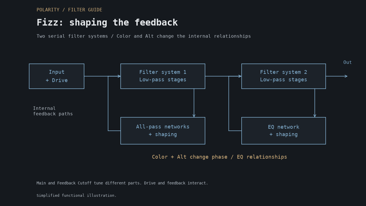
Simplified functional illustration: the feedback paths shape which parts of the sound are emphasized. Main Cutoff and Feedback Cutoff give you separate tuning controls.
Rasp: a moving edge around the cutoff #
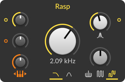
Rasp is another Bitwig Character design. It adds movable resonant peaks around a low-pass or band-pass core. Brightness changes the relationships between these peaks; it is more than a simple treble boost. Bitwig 5.1 release notes
Try this: feed it a harmonically rich bass, keep resonance restrained, and modulate Brightness with a short envelope. Audition the Brightness modes to find a movement that supports the phrase. Then introduce more resonance if you want a stronger growl or scream.
Rasp is a useful candidate when the middle of a sound needs expression. For a bass that must retain a stable sub, try applying it to a separate upper layer and listen to both layers together.
Brightness changes the resonance pattern. Feedback Limit, ranging from 35% to 100%, gives you another way to shape the feedback character. Check output level separately: it does not set a loudness ceiling for your track.
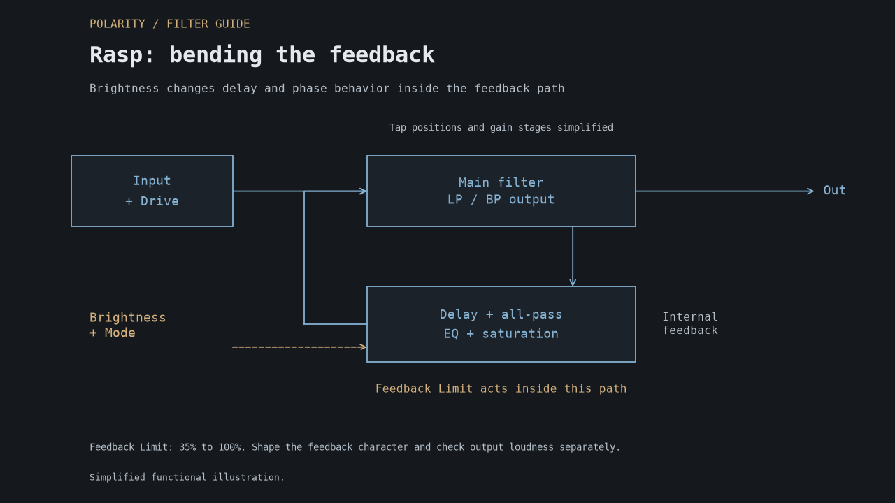
Simplified functional illustration: compare Shift, Double and Gravity to hear different kinds of Brightness movement through the feedback pattern.
Ripple: let feedback shape the result #
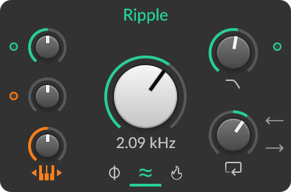
Ripple is Bitwig's more unruly Character option, with bipolar feedback and controls for the internal feedback and feedforward paths. It can produce strong resonances, subharmonic behavior, and distortion; no particular vintage synthesizer is identified as its model. Ripple module reference
Try this: use a simple sustained note or a sparse percussion loop. Raise feedback slowly, then move the feedback cutoff while leaving the main cutoff steady. Compare positive and negative feedback. Change one control at a time so you can hear which interaction is useful.
Choose Ripple when you want the processor to contribute unexpected tone, pitches, or unstable movement. Record several passes once you find an interesting region. Input level matters, so audition it at the level it will receive in the track.
Ripple's Feedback Gain spans -100% to +100%, with Earth, Wind and Fire models. FB Alt and FF Alt interact, so revisit each after changing Model. A useful listening order is Model, the two cutoffs, signed Feedback Gain, then the Alt switches and Drive.
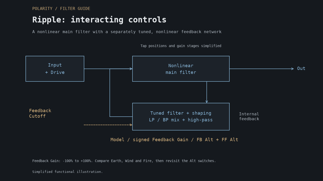
Simplified functional illustration: a separately tuned feedback path interacts with the main filter. Input level, Model and the Alt switches all contribute to the result.
Four more filters in The Grid #
The Grid's Filter category also contains these four utilities, in addition to Filter+'s ten-module selector. Together, the two tables cover all 14 Filter modules. Grid reference
| Module | When it is useful |
|---|---|
| Low-pass | Simple non-resonant darkening, or smoothing a changing control signal |
| High-pass | Removing low-frequency buildup in a patch or feedback path |
| All-pass | Changing phase; mix with a dry signal to explore cancellations and phaser-like effects |
| Dome | Building frequency-shifting and signal-analysis patches using its quadrature, magnitude, and phase outputs |
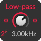
For ordinary brightness shaping, start with Low-pass or High-pass. All-pass becomes especially useful when signals are combined. Dome belongs to more specialized patch construction and can wait until you need those signals.
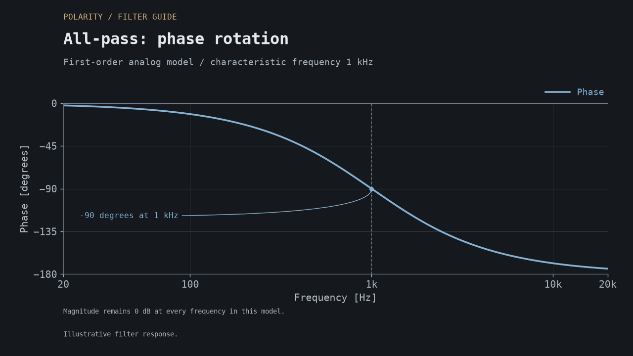
An all-pass can change the relationship between signals without changing its own magnitude response. This first-order example keeps magnitude at 0 dB; the graph shows phase instead.
How to compare filters without fooling yourself #
In Filter+, the waveshaper comes before the filter. Bypass it for the first comparison, set LFO and audio modulation amounts to zero, and use the same input signal. Add those parts back once you have chosen the filter. My Filter+ guide explains the routing.
Compare similar shapes and slopes first. A four-pole low-pass against a band-pass tells you more about those shapes than about their circuit character. Start with little resonance and drive, then raise one at a time. Equal knob positions do not guarantee equivalent behavior across models.
Match the output loudness after each change. Louder easily sounds more impressive. Check three things: the attack, the sustained body, and how much space the sound leaves for the rest of the track.
For played synth voices, try keytracking so cutoff follows the notes. This can keep the tonal balance more consistent across the keyboard. The filter keytracking article explains how to target harmonics.
What about CPU and sound quality? #
Choose the filter for the sound first, then check the cost in your patch. More voices, longer releases and voice stacking can make the same filter much more demanding.
Ripple's Lo-Fi / Low Quality option reduces processor load and changes the tuning. Compare both settings in the track and keep the one that sounds right. Bitwig 5.1 release notes
If a patch becomes expensive, compare it with fewer active voices and less voice stacking, then try a simpler filter that still does the job. Use Bitwig's DSP meter with the same notes, release times, sample rate, and buffer settings. Judge the result in the arrangement: the useful filter is the one that gives the part the movement and space it needs.